TŘINECKÉ ŽELEZÁRNY, a.s.
Třinec / Czech Republic
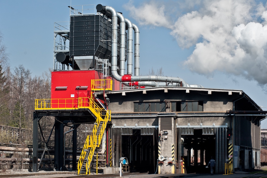
Coal unloading pit and tippler no. 3 and 4 dust extraction in the Třínecké železárny plant
CIPRES FILTR BRNO, s.r.o. in association with TENZA, a.s., under the name TENZA – CIPRES have become the general contractor of the “coal unloading pit dust extraction” and “Tippler no. 3 and 4 dedusting” projects for Třinecké Železárny, a.s. The above-mentioned contracts are very significant and will contribute to the continuing trend of environmental protection and industrial modernization.
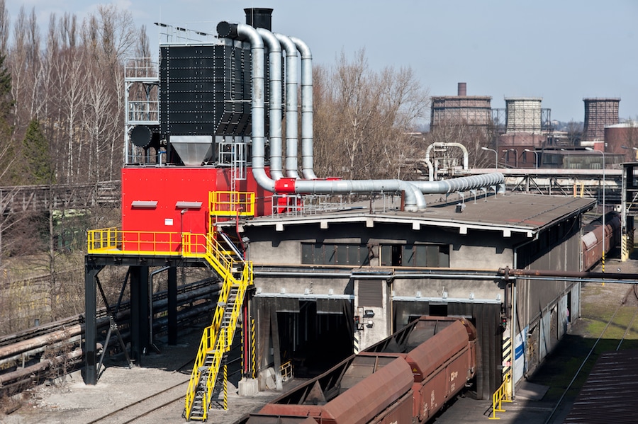
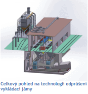
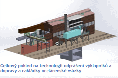 Overview of dedusting technology, and steelwork batches conveyance and loading. Both of these environmentally aware projects cost almost 100M CZK and their primary aim is improving workers’ health conditions and greatly reduce emissions from the technological processes. The solution is installing sufficiently efficient filtration devices with minimum operational breaks, which comply to all health and safety regulations and technical requirements.
90 % of all eligible costs was covered by the funds from the Operational Programme Environment, while the rest will be covered by company resources. Both contracts were finished as scheduled in early 2015.
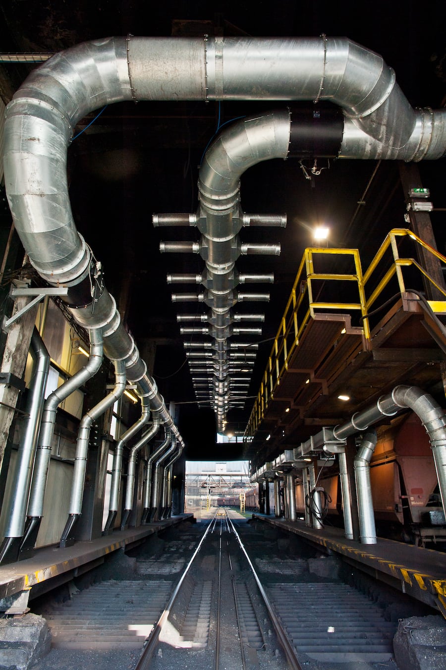
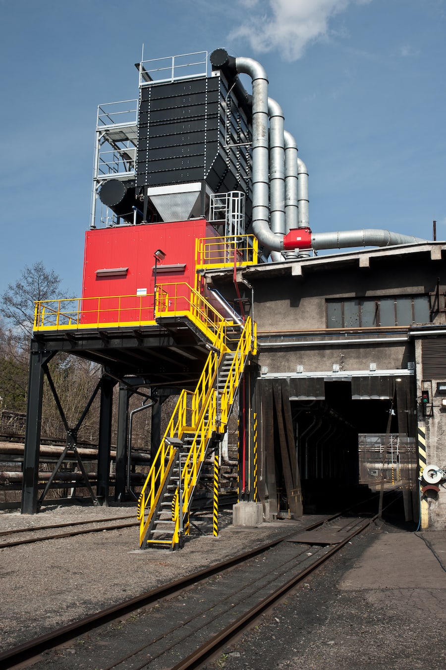
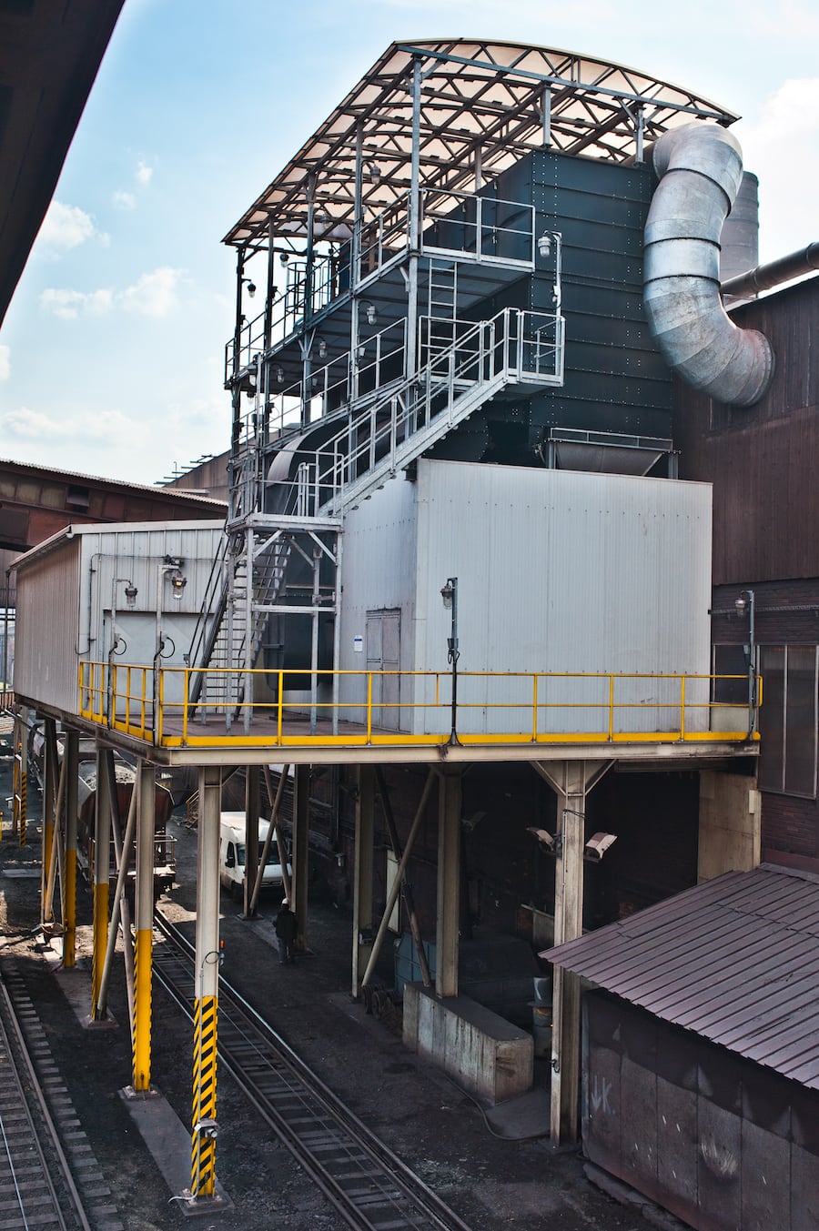
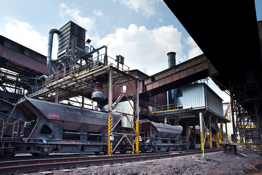
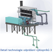
 The “Tippler no. 3 and 4 Dedusting” project comprised of filtration technology made of new individual filtration units for individual tipplers and conveyors of steelwork batches. The filtration unit for the tipplers is situated on a new steel platform next to the tippler shed. The steelwork batches are conveyed from mining site into railway wagons. A new filtration unit situated on a new steel platform above the railroad takes care of dust extraction.
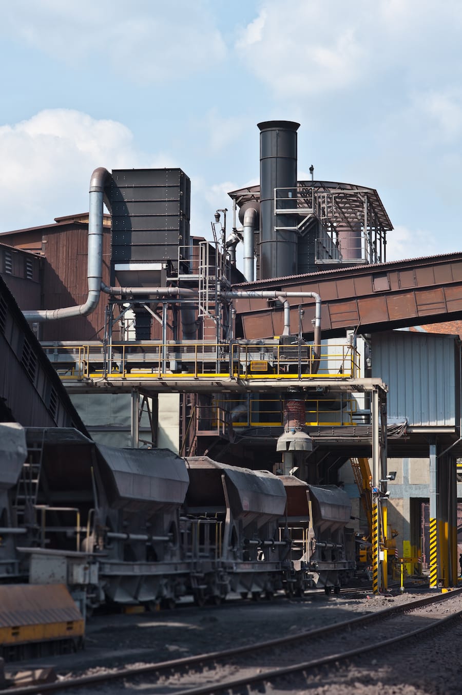
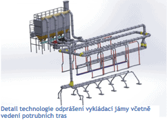
The “Coal Unloading Pit Dust Extraction” project comprises of dust extractor situated under the ceiling of the unloading pit, dust extractor near the hoppers of six drum feeders and the conveyor hopper dust extraction.
The aim of this contract was improving workers’ health conditions and also significant reduction of air pollution caused by the operation. Dust extraction must be carried by covering the dust sources or alternatively placing extraction attachments near the dust source and extract all air with dust particles in the vicinity.
Before the project
Tipplers site
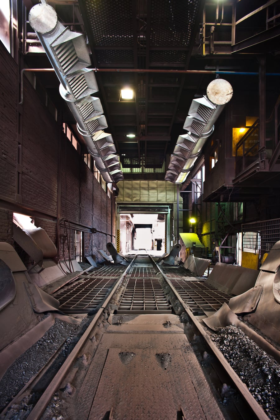
The no.3 and 4 tipplers are industrial sheds with a siding track leading inside them. There is a hopper in the middle of each shed, into which two wagons unload the conglomerate from each side. The conglomerate is then conveyed into a screening plant. The sheds are open on the both short sides of the building, where the siding track goes through. The two sheds are carried by a steel construction and the walls are made of fair faced bricks and timber. The tipplers were dedusted with an unsuitable dust extraction device. The steel batches were loaded into wagons via hopper, with no dust extraction. When the wagons were loaded or unloaded, a great deal of dust was produced, which escaped into the surrounding area.
Coal unloading pits
The coal for coke production was transported into the coking plant in automatic-discharge wagons. The coke was then stored, ground, discharged and conveyed in the coal service operations center.
The coal was discharged into the coal unloading pit. The gable walls are opened for the wagons to pass through, and throughout the whole shed, there are two rails with rail wagons. Each rail has two unloading spaces with 200x200mm grills at the rail level.
Unloading is usually carried on one of the two spaces of each rail. There are four containers underground, each with volume capacity of two rail wagons. Each container is equipped with plate closures and drum feeders. The coal used to be conveyed into enclosed coal landfills or to coal mills. At that time, there was no dust extractor at the coal unloading pit.
Emission limits
The operator has agreed to reduce emission limits by extracting dust and solid pollutants to the following values:
Emission limits for the coal unloading pit – max. 10 mg/m3 with the extracted air volume of min. 22,2 m3ef/s (80 000 m3ef/h).
Emission limits for tipplers – max. 20 mg/m3, with annual average of max. 10 mg/m3 with the extracted air volume of min. 30,6 m3ef/s (110 000 m3ef/hod) for both tipplers and 3,3m3ef/s (12 000 m3ef/hod) for the conveyors and steelwork batch loading sites.
Construction range
The tippler dedusting contracts cost 47.5 million CZK and it comprised of not only tippler no.3 and 4 dust extraction systems, but also delivering automatic wagon powering as well as complete construction of micropiles, steel construction above the rails, external cladding restoration of the tippler buildings, automatic high-speed doors for preventing air draft, steel-working batches transport and loading, and additional dust extraction system.
The coal unloading pit contract cost 51.3 million and it comprised of filtration technology with similar capacity to the tippler dust extraction project. It was, however, more technologically difficult, as the extracted dust is explosive and the inner piping walls together with the filter fabric are classified BE3N1 – high danger of inflammable dust explosion. The hazardous area is classified in accordance with ČSN EN 60079-10-2 – zone 20.
Both aforementioned contracts overlapped, because they needed to be finished and operational until January 2015. The contract overlap caused increased pressure on construction managers and our production capacity, which needed to ship out filtration technology for both contracts with minimum intervals in between.
Filtration device description
 Tipplers filtration device
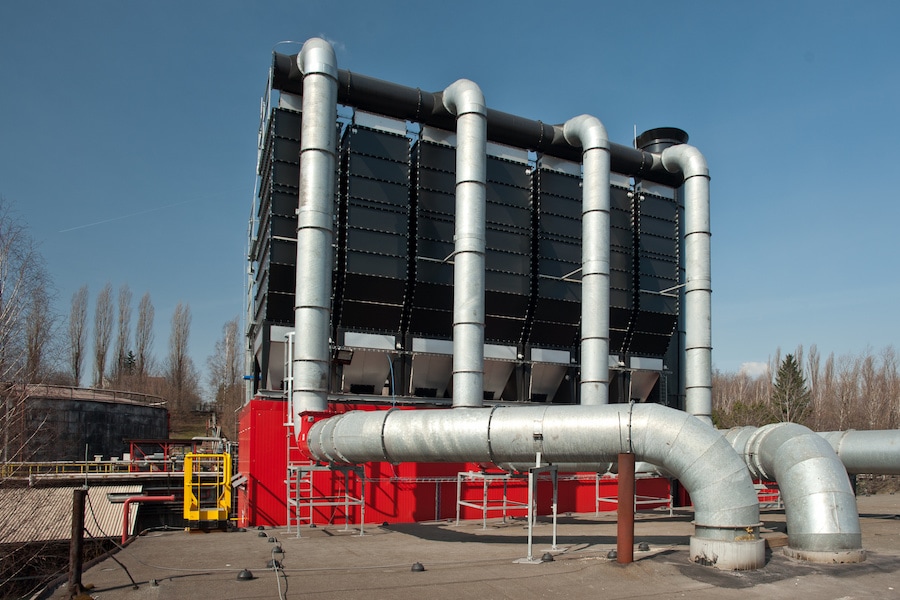
The filter for tipplers no. 3 and 4 dust extraction is situated on a steel platform next to the tippler sheds at a height approx. of 6.5 meters. The filter is made of fabric, operates under negative pressure, has a cabinet construction and sits on a supporting steel construction. Dust-laden air enters the filter at its upper part and filtered air exits through the bottom part, which allows controlled top-down air circulation inside the device. This eliminates dust deposits in the upper part, which reduces pressure loss in the filter medium.
The filter medium is regenerated by a JET system – with compressed air It is controlled with a timing unit, which starts up according to the filter’s pressure unit. The filter’s discharge chute and the screw conveyor are heated, thermally insulated with mineral wool and encased with aluminum sheets.
Dust from the discharge chute is carried away by a screw conveyor. Pneumatic double flap functions as a pressure relief valve. From there, dust is carried through pipes into a container on the ground. Containers with dust are transported with cars onto a secured homogenization landfill.
The extracted air is transported by a radial high-pressure fan, which is flexibly mounted on the same steel construction as the fabric filter. The fan is enclosed with sound-absorbing walls with inner absorption. Input and output are equipped with absorbing insoles and the fan is controlled with a frequency converter.
| Filter: 2x CARM GH 15/4/(9)8/17 ODL Š | ||
| Parameter | Unit | Value |
| Extracted air volume | m3ef/hod | 110 000 |
| Fan power consumption | kW | 250 |
| Filter area | m2 | 1680 |
| No. of filter elements | ks | 960 × 1,75 m2 |
| No. of filter chambers | ks | 8 |
| Filtration rate | m3/m2/min | 1,09 |
| Residual drift | mg/Nm3 | 1 – 5 max 10 |
| Est. filtered dust | t/h | 0,2 – 0,6 |
| Operating temperature | °C | -30 to +30 |
| The technical level of the offered technology | According to the BAT standards | |
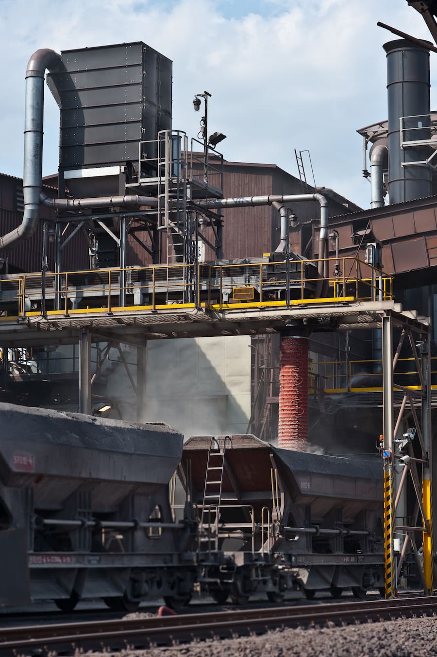
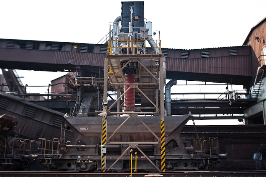
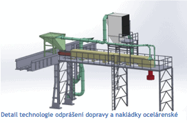
A special fabric filter was designed for dust extraction of hoppers and feeding pipe and it is placed on a steel construction for the conveyor belt. Dust sources are connected with pipes to the filter input. Filtered air is blown to the fan intake, which is situated on the ground next to the concrete bridge. Filtered air is blown through vertical exhaust pipe placed on the bridge to the outside environment above the bridge.
Dust from the filter is discharged through a hopper on a belt conveyor. The fabric filter hopper is heated with electric heaters, thermally insulated with mineral wool and encased in aluminum sheets.
| Filter: CARM GH 10/2/(7)6/17/ODL; F36 SD | ||
| Parameter | Unit | Value |
| Extracted air volume | m3ef/hod | 12 000 |
| Max fan power consumption | kW | 22 |
| Filter area | m2 | 210 |
| No. of filter elements | ks | 120 × 1,75 m2 |
| No. of filter chambers | ks | 1 |
| Filtration rate | Nm3/m2/min | 0.95 |
| Residual drift | mg/Nm3 | 1 – 5 max 10 |
| The technical level of the offered technology | According to the BAT standards | |
Coal Unloading Pit Dust Extraction
The main part of this dust extraction device is a fabric filter with a fan. These devices are placed on a new steel structure behind the coal unloading pit building, over the rails no.1940 and 1921. The solution was designed to have the shortest piping possible. At a height of 7 meters above the ground, there will be a reinforced concrete platform set up for proper access to the device.
The extraction points are covered and equipped with extraction extensions connected to the extraction ducts with regulation elements for regulating individual branches. Pipeline is optimally routed to be as short as possible, while using existing structures as efficiently as possible.
The extracted air is transported by a radial high-pressure fan, which is flexibly mounted on the same steel construction as the fabric filter.
Exhaust pipes for blowing filtered air out is connected to the fan with an exhaust head output. Sound isolation is installed in the exhaust pipes to reduce noise levels.
Filtered dust slides from the filter through a discharge grate and into a container. Before the dust reaches the container, it is humidified in a mixer.
The entire space beneath the filtration device hopper is covered with metal sheets, thermally insulated and kept under a 5°C temperature. A noise-protection wall is installed to prevent noise from the fan from spreading.
| Filter: 7x CARM GH 15/1/(8)7/17 ODL OSEX 3M 2xŠ 1xRP1 50/20-8 | ||
| Parameter | Unit | Value |
| Extracted air volume | m3ef/hod | 80 000 |
| Max fan power consumption | kW | 160 |
| Filter area | m2 | 1286 |
| No. of filter elements | ks | 735 × 1,75 m2 |
| No. of filter chambers | ks | 7 |
| Filtration rate | m3/m2/min | 1,03 |
| Residual drift | mg/Nm3 | 1 – 5 max 10 |
| Operating temperature | °C | -30 to +30 |
| The technical level of the offered technology | According to the BAT standards | |
CIPRES FILTR BRNO s.r.o.
PHOTOS FOR REFERENCE