TŘINECKÉ ŽELEZÁRNY
References
Třinec / Czech Republic
CIPRES FILTR BRNO, s.r.o., in a consortium with the Brno-based company TENZA, a.s., under the name “TENZA – CIPRES”, has become the main contractor for the projects “Dust control at the coal unloading pit” and “Dust control at tippers 3 and 4” for the client TŘINECKÉ ŽELEZÁRNY, a.s. These are major contracts which, alongside other environmental projects undertaken by the client, will make a significant contribution to the ongoing trend towards environmental improvement and the modernisation of the environment in which industrial activity takes place.
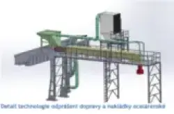
An overview of the dust extraction technology for the tippers and the transport and loading of steelmaking charge. Both projects, with a total value of nearly CZK 100 million, are environmental projects whose main aim is to improve health and safety conditions for operating staff and to significantly reduce emissions of particulate matter from industrial processes into the atmosphere. The solution involves sufficiently effective filtration equipment, installed whilst minimising operational downtime whilst complying with all other health and safety regulations and operational technical conditions.
90 per cent of the eligible costs for both projects will be covered by a grant from the Environment Operational Programme; the remaining costs will be covered by the operator from its own funds. Both contracts are scheduled to be completed by February 2015.
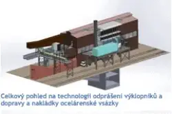
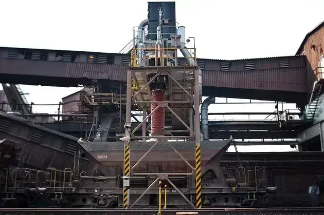
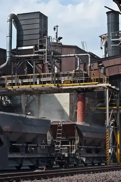
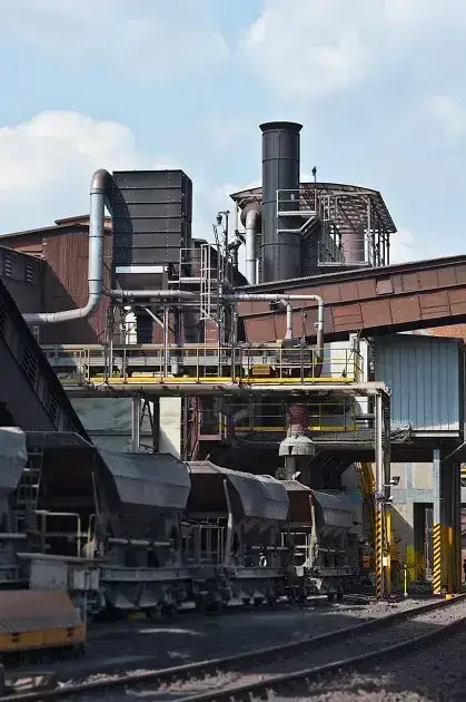
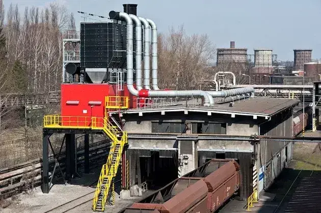
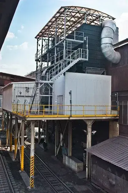
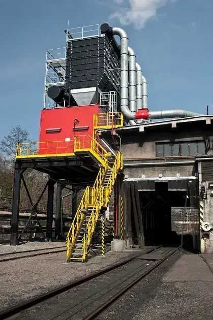
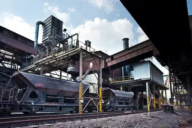
The subject of the contract ‘Dust removal from tippers 3 and 4’ is the installation of filtration technology in the form of new, stand-alone filtration units for the individual tipper workstations and the workstation for the transport and loading of steelmaking charges. In the case of the tipper worksite, the filtration unit is situated on a new steel platform next to the tipper hall. The transport and loading of steelmaking charge involves loading the charge from the ore stockpile into railway wagons. Dust control for this operation will be provided by a new filtration unit situated on a new steel platform above the tracks.
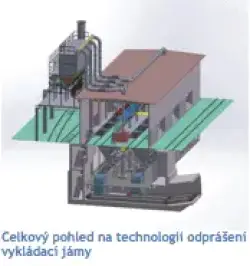
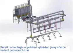
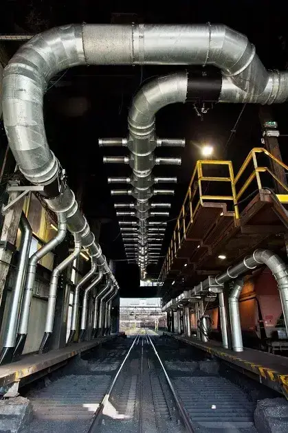
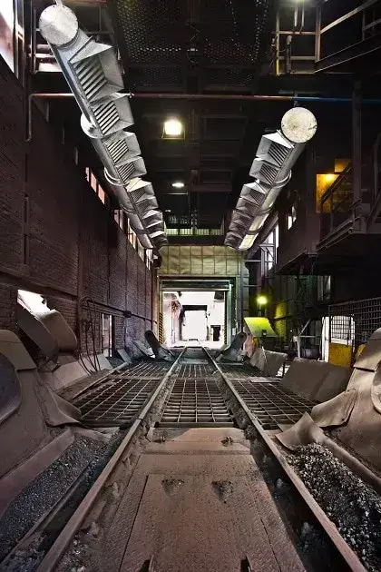
The scope of the contract ‘Dust control for the coal unloading pit’ comprises the construction of a dust extraction system in the unloading area above the grate and beneath the ceiling of the unloading pit building, as well as the installation of an extraction system for the hoppers of six drum feeders feeding into the collection belts, and the installation of an extraction system for the collection belt chutes.
The aim of both construction projects is to improve health and safety conditions for the client’s workers and to significantly reduce air pollution caused by operations. Dust control must be achieved by covering dust sources or, where appropriate, by positioning extraction nozzles near dust sources and extracting dust-laden air.
Tipper
workplace The tipper buildings No. 3 and 4 are hall-type structures through which the sidings’ track runs. In the centre of the hall, beneath the track, there is a hopper into which wagons tip their loads from both sides. From the hopper, the conglomerate is then conveyed by belts to the sorting plant. The hall is currently open at both shorter ends, through which the sidings run. It is a steel structure; part of the walls consists of exposed fired-brickwork, whilst in the upper section the brickwork is replaced by cladding made of wooden planks. Dust extraction from the tipper hoppers is currently provided by substandard dust extraction equipment. The steelmaking charge is loaded into wagons on the track via a hopper situated on the energy bridge, without any dust extraction. These areas are a source of dust when wagons are tipped or loaded, as dust escapes freely into the surrounding area.
Coal
Unloading Pit Work Area Coal for coke production is delivered to the coking plant in self-dumping railway wagons. After unloading, the coke is stored, ground, metered and transported by belt conveyor to the coal service operations centre.
Coal is unloaded from the self-dumping wagons at the coal unloading pit. The gable walls of the building are open to allow railway wagons to pass through; two through tracks run through the building and the railway wagons are pulled by a pulling mechanism. On each track, there are two unloading points equipped with 200 x 200 mm grates at track level.
Unloading is usually carried out at one of the two points on each track. Below ground level, there are four hoppers, each with a capacity equivalent to two railway wagons. All storage bins are fitted with plate-type shut-off valves and drum feeders. From the transfer station, the coal is transported to covered coal storage facilities or to the coal mill. At present, the coal unloading pit is not equipped with a dust suppression system.
Emission limits
The operator has undertaken to ensure that the construction of a new dust extraction system will reduce the emission limit for particulate matter to the following values:
Emission limits for the coal unloading pit dust extraction system at the outlet downstream of the filter – max. 10 mg/m³ at an air extraction rate of at least 22.2 m³ef/s (80,000 m³ef/h).
Emission limits for the dust extraction system of the tipping hoppers at the outlet downstream of the filter for each dust extraction unit – max. 20 mg/m³, with an annual average of max. 10 mg/m³, with a minimum air extraction rate of 30.6 m³ef/s (110,000 m³ef/h) for the dust extraction systems of tippers 3 and 4, or 3.3 m³ef/s (12,000 m³ef/h) for the dedusting system for the transport and loading of steelmaking charge.
Scope of construction
The entire construction project for the tipper dust extraction system at TŘINECKÉ ŽELEZÁRNY, valued at 47.5 million crowns, comprises not only the dust extraction technology for tippers 3 and 4, but also of the complete civil engineering works comprising micropiles, steel structures above the existing tracks, refurbishment of the perimeter cladding of the tipper building, the installation of high-speed automatic doors to prevent draughts, and a solution for the transport and loading of steelmaking charge, including a separate dust extraction system, which also involves the supply of equipment for the automatic shunting of wagons.
The unloading pit dust extraction project, with a value of 51.3 million crowns, involves the construction of filtration technology with a capacity similar to that of the tipper dust extraction project. However, correctly managing the design of the technology is more challenging, as the dust being extracted is explosive and the internal spaces of the extraction ductwork and fabric filter are classified as BE3N1 – areas with a high risk of explosion from combustible dusts. Classification of hazardous areas in accordance with ČSN EN 60079-10-2 – Zone 20.
The two contracts overlap in terms of implementation, as they must be handed over to the client for trial operation in January 2015. In addition to placing increased pressure on the construction managers, the overlap between the contracts also has an impact on the production capacity of the technology supplier, who must dispatch both deliveries of filtration technology to the site with minimal time between them.
Odprášení výklopníků
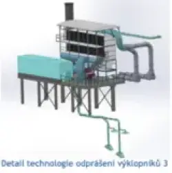
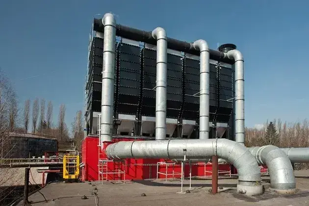
Filtr pro odprášení výklopníků 3 a 4 je situován na nové ocelové plošině vedle haly výklopníků 3 a 4 ve výšce cca 6,5 m. Filtr je látkový, podtlakový, skříňové konstrukce, usazený na nové nosné ocelové konstrukci. Vstup znečištěné vzdušiny je proveden v horní části skříně, výstup přefiltrovaného vzduchu bude ve spodní části „čisté strany“ filtračního zařízení, což zajišťuje usměrněné proudění filtračním zařízením v orientaci shora – dolů. Je tak eliminována možnost držení odprašků ve vznosu, z čehož plyne dosažení nižší provozní tlakové ztráty filtračního média.
Jeho regenerace je prováděna systémem JET – tlakovým vzduchem. Řídí ji časovací jednotka s možností spouštění podle tlakové ztráty filtru. Výsypka filtru je spolu se šnekovým dopravníkem opatřena elektrickým vytápěním a obě části tepelně izoluje minerální vlna a kryje hliníkový plech.
Odprašky jsou ze žlabové výsypky vynášeny šnekovým dopravníkem. Jako tlakový uzávěr je uvažována pneumaticky poháněná dvojklapka. Od ní jsou odprašky svedeny potrubním skluzem do bikranové nádoby uložené na zemi. Nádoba s odprašky bude odvážena nákladními automobily na zabezpečenou homogenizační skládku.
Dopravu odsávané vzdušiny zajišťuje radiální vysokotlaký ventilátor, pružně uložený a umístěný na stejné ocelové konstrukci jako látkový filtr. Ventilátor je umístěn mezi zvukoizolační stěny s vnitřní absorpcí. V sání a výtlaku jsou tlumící vložky, rozběh ventilátoru je řešen pomocí frekvenčního měniče.
| Filtr: 2x CARM GH 15/4/(9)8/17 ODL Š | ||
| Parametr | Jednotka | Hodnota |
| Množství odsávaného vzduchu | m3ef/hod | 110 000 |
| Příkon ventilátoru | kW | 250 |
| Filtrační plocha | m2 | 1680 |
| Počet filtračních elementů | ks | 960 × 1,75 m2 |
| Počet filtračních komor | ks | 8 |
| Filtrační rychlost | m3/m2/min | 1,09 |
| Garantovaný zbytkový úlet | mg/Nm3 | 1 – 5 max 10 |
| Předpoklad množství zachyceného prachu | t/h | 0,2 – 0,6 |
| Konstrukční teplota | °C | -30 až +30 |
| Technická úroveň nabízené technologie | dle standardů BAT | |
A fabric filter has been designed to remove dust from the hopper, discharge chute and filling spout; it is mounted on a new steel structure for the conveyor belt. The dust sources are connected via ducting to the filter inlet. The cleaned air is channelled through ducting to the intake of the fan, which is situated on the ground next to the footbridge on a concrete foundation. The purified air is discharged via a vertical exhaust duct anchored to the footbridge, venting into the open air above the level of the footbridge.
The dust particles captured by the filter are conveyed from the hopper via a shut-off valve onto a covered conveyor belt. The fabric filter hopper, heated by electric heating elements, is thermally insulated with mineral wool insulation covered with aluminium sheet.
| Filter: CARM GH 10/2/(7)6/17/ODL; F36 SD | ||
| Parameter | Unit | Value |
| Airflow rate | m³ef/h | 12,000 |
| Max. fan power consumption | kW | 22 |
| Filter area | m² | 210 |
| Number of filter elements | pcs | 120 × 1.75 m² |
| Number of filter chambers | pcs | 1 |
| Filtration rate | Nm³/m²/min | 0.95 |
| Guaranteed residual emissions | mg/Nm³ | 1–5, max. 10 |
| Technical standard of the technology offered | in accordance with BAT standards | |
Dust control at the coal unloading pit
The main component of the dust extraction system is a fabric filter with a fan. These units are situated on a new steel structure behind the coal unloading pit building, above tracks Nos. 1940 and 1921. The location has been chosen so that the extraction pipework routes are as short as possible. A reinforced concrete platform will be erected 7 metres above ground level to provide access to the equipment.
The extraction points are covered and fitted with extraction nozzles connected to the extraction pipework, which includes control valves to regulate the individual branches. The pipework routes are optimised – taking the shortest possible path whilst making maximum use of existing structures.
The transport of the extracted air is provided by a radial high-pressure fan, which is flexibly mounted and situated on the same steel structure as the fabric filter.
The exhaust duct for discharging the filtered air is connected to the fan outlet and terminated by an exhaust nozzle. To reduce noise emissions, silencers will be installed in the exhaust duct.
Dust removal from the filter is achieved via a chute through a discharge grate into a hopper. Before being discharged into the hopper, the dust is rendered dust-free by being moistened in a mixing screw.
The entire space beneath the filter unit’s discharge hopper is clad with sheet metal, thermally insulated and maintained at a temperature of +5°C. A protective noise barrier has been designed to prevent the spread of noise from the extraction fan.
| Filter: 7x CARM GH 15/1/(8)7/17 ODL OSEX 3M 2xŠ 1xRP1 50/20-8 | ||
| Parameter | Unit | Value |
| Air extraction volume | m³ef/h | 80,000 |
| Max. fan power consumption | kW | 160 |
| Filter area | m² | 1286 |
| Number of filter elements | pcs | 735 × 1.75 m² |
| Number of filter chambers | pcs | 7 |
| Filtration rate | m³/m²/min | 1.03 |
| Guaranteed residual emissions | mg/Nm³ | 1 – 5, max. 10 |
| Design temperature | °C | -30 to +30 |
| Technical standard of the technology offered | in accordance with BAT standards | |
CIPRES FILTR BRNO s.r.o.

© 2026 CIPRES FILTR BRNO s. r. o.
All rights reserved